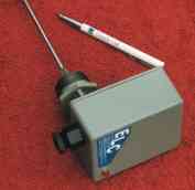
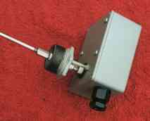
Electronic Boiler Level Control
Technical Data
Size: Case 115mm High x 90mm Wide x 55mm Deep, Probe length 300mm
The Level Control: This level control is intended for use in high-pressure hot water boilers, it will of course work equally well in low-pressure boilers or boilers with an expansion tank. It functions by detecting the resistance of the water between the very high quality stainless steel probe and the boiler chassis. The varying resistance of the water causes a Cmos circuit to switch, giving direct control with no moving parts
The Output: Is a low voltage relay with volt free double pole change over contacts. One contact switches the output the other, switches the neon low water indicator. Using change over contacts on the output enables switching of rising or falling water levels, or differential water levels using two controllers
Isolation: A 240v Ac mains isolating transformer reduces the working voltage down to 12vdc with one side of the secondary winding tied to earth potential to remove any possibility of a shock hazard. In fact the voltage between the probe and chassis is a mere 0.3v Ac at a current of 2.5ma
Electrolysis: The low voltage/current at probe level is to reduce the effect of electrolysis to an absolute minimum. The electrolysis action present in all electrical circuits of this type is reduced still further by using an Ac voltage so that neither the probe or the chassis will become a charged potential, keeping both as clean as possible
It is most important that an electrical earth is fitted to the unit
Experience has shown that the probe stays clean for many years, and should never need cleaning in normal conditions. However we do recommend fitting the level control through a dart union to facilitate removal for inspection. The probe must not be allowed to stay in contact with the boiler or pipe walls, as then of course it could not read the resistance of the water. As a general rule keep a gap if about ½" between the probe and any part of the boiler or pipes, further if possible
Lockout: Should the water level fall below the probe level for more than 6 seconds the unit will go into the low level alarm lockout state, if the water is restored before the 6 seconds the unit will not lockout. This feature is incorporated to allow for pump surges airlocks etc. During the lockout condition the red neon will be turned on and will stay on until reset manually, this gives service engineers a direct indication of a low-level condition
Reset: To reset the unit simply turn off the power to it for a few seconds. However the unit will not reset if there is still a low-level condition. This type of semi automatic reset is used so that service engineers will not have to go looking for reset buttons after a low level condition. It also facilitates automatic starting after the boiler has been turned off for some time, after a breakdown or at the start of a heating season
Fitting: Into the flow at the top of the boiler is via a 1¼" bush. It is strongly suggested that the unit is connected through a 1¼" dart union to a short stub of 1¼" pipe welded directly into the boiler flow in a horizontal position, this will enable the unit to be removed for inspection. Do not fit a valve between the unit and the boiler